How Flexible Circuit Boards Handle Vibrations and Shocks
Flexible Circuit Boards Handle Vibrations
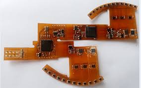
As the name suggests, flexible circuit boards are pliable and can bend to fit their designated systems. This flexibility allows them to absorb vibrations and shocks more effectively than rigid PCBs, resulting in longer product lifetimes and fewer failures during operation. Additionally, they can dissipate heat more effectively and fold up into compact shapes to reduce package size and weight.
A flexible circuit board consists of copper tracks and pads on a non-conductive base material such as polyimide. It is then coated with an electrically conductive epoxy resin or acrylic adhesive layer. This layer bonds the thin rolled annealed copper conductors to the base layer. This copper is then etched to remove excess metal and leave the required trace widths. After etching, manufacturers may add a copper foil shield or a cross-hatched pattern to prevent damage during handling and manufacturing processes. The copper foil also acts as a power and ground plane to minimize signal loss during dynamic flexing.
The layers of a flexible circuit board can vary, depending on how much flexibility is needed in the final system. The number of copper traces, layers of adhesives and laminates, and the type of base material can be configured to meet specific requirements. For example, the layer stackup can be designed to handle static or dynamic flexing, with careful impedance control and routing for signals in radio, timer, and digital applications. The flex circuit can also support different connectors and components, including crimped contacts and ZIF connections.
How Flexible Circuit Boards Handle Vibrations and Shocks
Rigid flex boards combine rigid and flexible sections of the circuit board to allow for a more customizable design with greater stability. Rigid sections can support heavy components or those with a lot of solder joints, while the flexible section can flex to accommodate tighter space requirements. Rigid flex circuits can also feature high density device populations and minutely narrow lines, allowing for more components to be fitted into a smaller package size.
Despite their differences, flex and rigid-flex circuits share many common features. Both can be used in dynamic or static flexing applications and can be made to withstand hundreds of thousands of cycles of bending and folding. They can also be manufactured using the same techniques as traditional rigid PCBs, which reduces testing time and wire routing errors.
To ensure a robust and durable circuit board, manufacturers must account for the stresses that the circuit board will experience during assembly and use. This includes understanding the dynamic flex stress that will be encountered and incorporating that information into the design. This will help the manufacturer optimize the layer stackup for dynamic flexing, selecting dielectric materials, copper weights and layers to match circuit needs. The manufacturer should also include underfills and stiffeners to reinforce certain areas of the circuit against cracking or fatigue.
A flex or rigid-flex circuit is usually categorized by its number of layers. The more layers there are, the more complex the circuit will be. The layers denote the number of copper traces, layers of adhesives or laminates, and polyimide materials. Some flex or rigid-flex circuits are single-sided, while others are double-sided and offer dual access to components. A flex or rigid-flex circuit should also feature a coverlay layer that protects the conductive copper and bonding pad surfaces.